In overhead line procurement, the most expensive items receive the most attention. Yet installation is often delayed by small mechanical interfaces: a crossarm that does not fit the pole, a clamp outside the conductor diameter range, a missing ball-and-socket fitting or bolts that are too short for the mounting plate.
A Burundi 30kV distribution project showed why steel poles, crossarms, insulator strings and line fittings should be reviewed as one pole-top assembly rather than separate catalog items.
Begin with the pole function
Not every pole carries the same load. The pole schedule should identify whether each structure is used as:
- a tangent or suspension pole;
- an angle pole;
- a dead-end or terminal pole;
- a branch pole;
- an equipment pole carrying a switch, fuse or transformer.
The required pole strength, crossarm reinforcement, insulator arrangement and foundation can change with the function.
In the project package, 16-meter galvanized steel poles were specified with strength classes expressed in daN. Before fabrication, the supplier should confirm what the stated load represents, the load application point, wind conditions, conductor tension, safety factor and foundation arrangement.
Why an octagonal steel pole needs its own mounting design
A tapered polygonal steel pole is different from a concrete or timber pole. Its diameter changes with height, and the flat faces affect how bands and mounting plates sit against the shaft.
The mounting package may include:
- shaped pole bands or U-bolts;
- backing and mounting plates;
- anti-slip features;
- galvanized bolts, nuts and washers;
- reinforcement plates or braces;
- equipment brackets;
- climbing steps or a controlled climbing system.
These accessories should be designed from the final pole drawing. Asking a factory to “include clamps” without giving the mounting height and local pole dimensions invites a mismatch.
Crossarms are structural components, not simple accessories
The tangent crossarm reference for the Burundi line used a 2,100mm phase spacing and hot-dip galvanized angle-steel members. The documented reference sizes included:
- L60 × 60 × 6mm angle steel;
- L80 × 80 × 6mm angle steel.
These dimensions are useful design inputs, but they do not automatically define every crossarm in the project. Angle and terminal crossarms must carry higher longitudinal forces and should be checked against the conductor tension, deviation angle, insulator arrangement and pole strength.
The final crossarm drawing should show:
- overall length and phase spacing;
- angle-steel or channel-steel sizes;
- hole diameters and center distances;
- insulator-string attachment points;
- pole bands and mounting plates;
- braces and reinforcement details;
- galvanizing and material requirements;
- installation orientation.
Separate the main conductor system from the guard-wire system
One recurring source of confusion is treating every pole-top clamp as a main-conductor fitting.
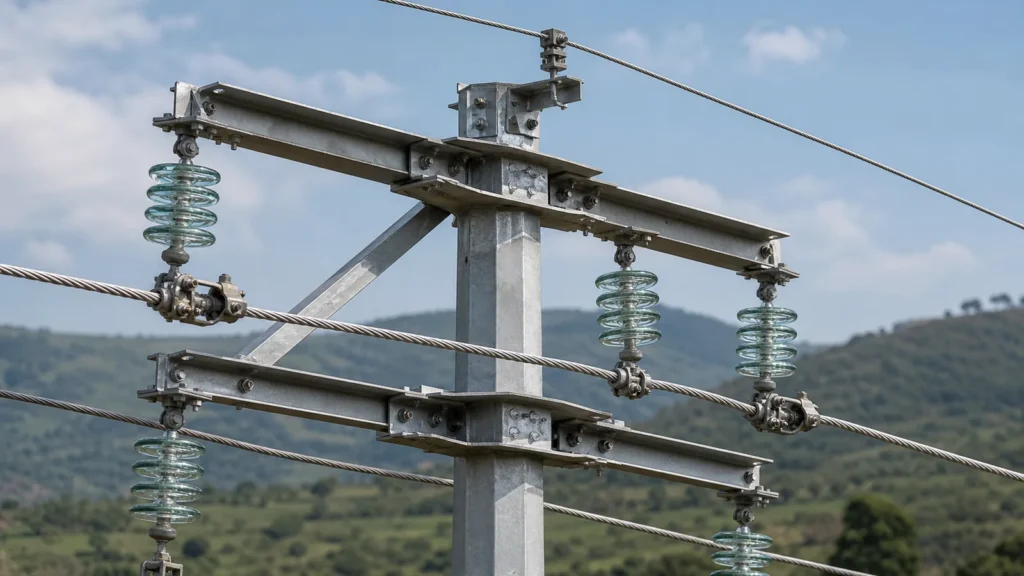
For an ACSR phase conductor, a tangent support assembly typically includes a suspension insulator string, suspension clamp and connection hardware. A dead-end assembly uses a tension insulator string and dead-end clamp to carry conductor tension.
A guard wire uses a different support and anchoring system. In the Burundi project documents, an M16 × 400 eye rod and anchor clamp belonged to the guard-wire assembly, not the ACSR phase-conductor suspension set.
This distinction affects both safety and ordering accuracy.
Need equipment matched to your project?
What belongs in a complete tangent assembly?
A typical tangent-pole phase-conductor set may include:
- galvanized crossarm;
- pole-mounting bands and plates;
- suspension insulator string;
- ball eye and socket clevis;
- short shackle or extension link;
- suspension clamp matched to the conductor;
- bolts, pins, washers and locking devices.
The exact configuration depends on the project standard and drawing.
What belongs in a complete dead-end or angle assembly?
A typical tension set may include:
- reinforced angle or dead-end crossarm;
- pole mounting and bracing system;
- tension insulator string;
- dead-end or wedge-type tension clamp;
- adjustable link where specified;
- ball-and-socket fittings;
- arcing horn where required;
- jumper connection fittings;
- complete bolts and locking hardware.
For one project reference, the tension insulator string used three disc insulator units and a complete set of galvanized connecting fittings. That configuration should be treated as drawing-specific, not copied to every 30kV network.
Match clamps to the conductor—not only to area
The notation ACSR 35/6 or ACSR 95/15 describes conductor construction, but the fitting manufacturer still needs the actual conductor standard and outside diameter.
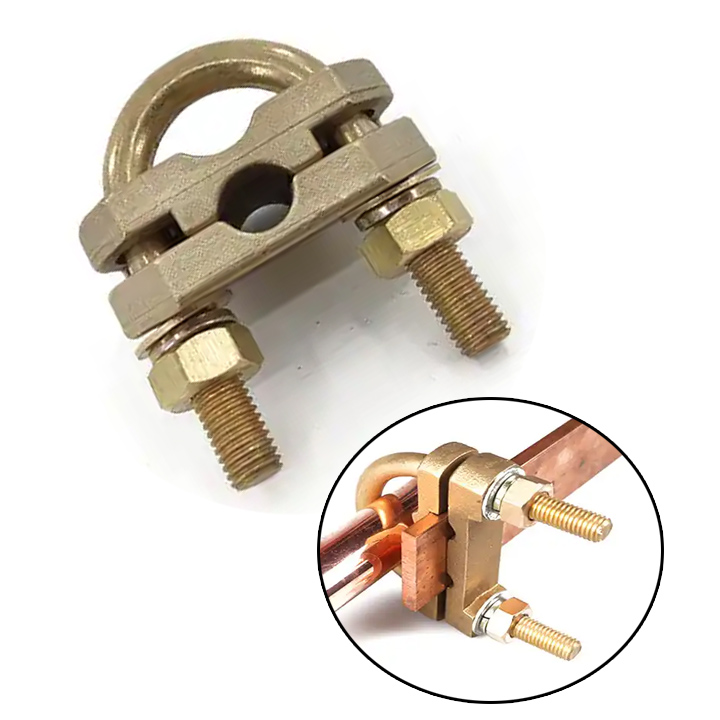
Two conductors with a similar nominal cross-sectional area may have different strand counts or diameters. A suspension clamp, dead-end clamp, PG clamp or compression sleeve must match the real conductor.
Send the following with the RFQ:
- conductor code and applicable standard;
- aluminum and steel cross-sections;
- strand construction;
- outside diameter;
- rated tensile strength;
- required mechanical load and installation position.
Galvanizing and corrosion control
For outdoor steelwork, specify the galvanizing standard, minimum coating requirement and treatment of drilled or cut surfaces. Bolts, nuts, washers, crossarms, braces and mounting plates should be included in the corrosion review—not only the main pole.
Packing also matters. Galvanized surfaces can be damaged by unprotected metal-to-metal contact during container transport. Crossarms and brackets should be separated, secured and marked by structure type.
Build and check one complete pole set before mass packing
A pre-packing trial assembly is one of the most effective quality checks for a mixed pole-line package. It can confirm:
- crossarm-to-pole fit;
- hole alignment;
- bolt length;
- insulator and clamp interfaces;
- equipment-bracket position;
- completeness of small fittings.
Photographs of the assembled set also help the site team understand how the parts relate to each other.
Younxin supports complete pole-line hardware packages based on BOQs, drawings and conductor data. Send your pole schedule and structure drawings for a coordinated quotation.
FAQ
Can the same crossarm be used on tangent and angle poles?
Not automatically. Angle and dead-end poles carry different mechanical loads and often need reinforced structures and different attachment points.
Is an M16 eye rod a phase-conductor support?
It depends on the drawing, but in this project the M16 × 400 eye rod was part of the guard-wire support and anchoring system, not the main ACSR suspension assembly.
Should climbing steps be included with the pole?
Only when required by the project and approved safety arrangement. Their position, projection, anti-climb provisions and fall-protection requirements should be confirmed before fabrication.